|
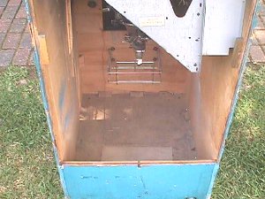
It's a beautiful day... just the right amount of sunshine... and it's cooled down to a pleasant 92 degrees, so I'm moving this project outside. Here's the old empty Ms Pac cab that has been waiting around all these years for some new wiring.
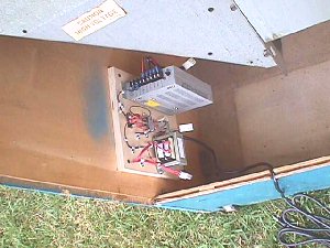 This is the typical Louisiana flood level control mounting. 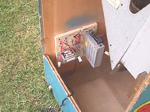 You can see that up to a foot of water wouldn't even slow this Ms Pac down. Of course, the player would need his rubber boots :-) 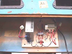 When the flood water is 4 feet high & rising more drastic measures are needed. Here's a high water installation that can even be plugged into a ceiling outlet allowing water as high as the monitor chassis. Forget the boots... don't try playing it, just be glad it'll still play after the water ebbs. 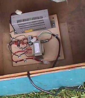 I'm going to just drop this "power center" into the cab bottom for this job, for ease in pic taking. You can mount it facing in just about any position that is convenient for you. 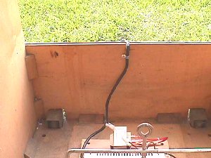 A 1/4" cable clamp will hold the ac line cord in place just in case someone decides to drag the game around via the cord, but it is not necessary & adds one more step to the quick removal process for t-shooting. Before doing any permanent wiring you'll need to decide where & how you want to mount your game bd. There are limitless ways to mount from using PCB feet to mounting on slide-in interchangeable panels. I used a lot of cheap strapping from Home Depot for stays. You can rip it in half & drill holes through it in 2 directions & screw it into any weak cab corners for bracing, as well as, cutting a slot in it to hold PCBs. Here's a pic of an assortment of small stays. 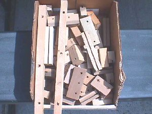 I'm going to mount the Ms Pac bd on a piece of plywood in a fashion similar to that of the "power center" using stays. Again, much easier to remove complete for any future t-shooting. 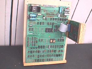 A piece of 1/2" or 5/8" BC plywood would work fine for this, but I had a piece of scrap cab ply just the right size, so I used it. The main bd is craddled in a stay at the bottom & fastened at the top with 2 PCB feet. I fastened another piece of scrap ply on a 90° & added stays to loosely craddle the auxiliary bd. 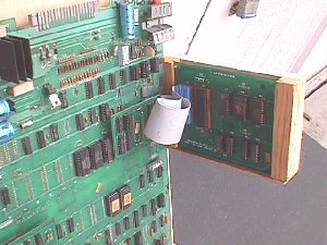 A scrap piece of thin paneling across the bottom keeps the auxiliary bd from sliding right through & the ribbon cable will keep it from sliding out the top when the cabinet is moved. 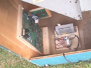 Putting a strip of plywood on the cab bottom in front of the premounted bd will hold the bottom in place & 2 screws easily fasten the top. Should the bd need to come out some time in the future, simply unplugging the edge connector & removing the 2 screws will allow it to be worked on at the service bench... instead of being a backbreaking job. With the 2 main components mounted it is safe to go ahead & finish the permanent AC wiring. The monitor isolated power line is an easy one... continuation of the two 18ga red wires from the "power center" up to the AC entry point for the monitor. 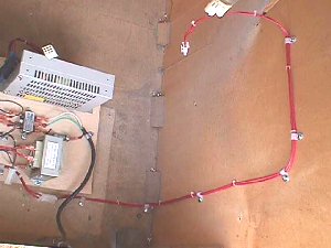 Simply measure the length you need, add the mating Molex 2 position receptacle on one end & the plug on the other... should be like an extension... cable tie the pair together & then fasten to the wall of the cab with cable clamps. 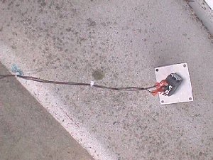 Adding the AC on/off switch line is next. This is where I use the pair of 18ga brown wires. Measure them from the power center plug to wherever you want your on/off switch to be located. I'm going to use one of the pre-mounted on/off switches in the existing AC switch hole in the top. I've cable tied the pair of wires together, crimped on a pair of .25 QDs & hooked them up before mounting. 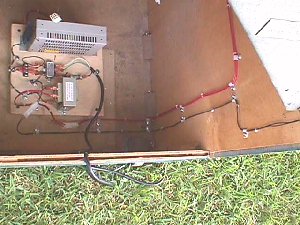 In cable clamping the switch line I ran it parallel for this demo, but you can join pairs together that are following the same route. 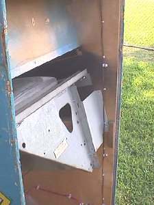 The switch line goes straight up the cab side to the mount. 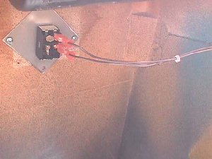 Leave a little slack at the top & you can use all 4 screws in the mounting plate, although, I've never had a problem using just 2. K... the only thing needed now is the switched AC power to light the marquee fluorescent. I've measured out a pair of 18ga blue wires & cable tied them together, added a Molex receptacle on the end for the marquee area & a pair of .25 QDs for the power distribution block. 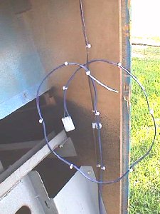 As I said before, all these lines can be combined & rather then run yet another cable clamped line I'm going to piggyback the switch line. 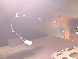 Once you pass the switch & branch out in to the marquee area you'll need to resume cable clamping to the outside cab wall. 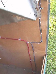 Using 3/8" cable clamps all 3 pair could easily be combined into one harness. Note: If one size cable clamp is too tight & pinching your wires, and moving up to the next size you find your wires are too loose & don't want to stay where you want them, you can secure them in place by putting a cable tie on either side of the clamp to prevent them from moving. 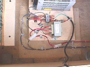 That's it! Switched AC power has been set into the cab. These same principles would apply no matter what game you were building. Next Chapter... DC Wiring ...Happy Gaming... |