|
Well... the last time I worked on this project it was a beautiful day... no such luck today, though :-( It's a raging Louisiana summer thunderstorm outside... cannons sounding just outside my window while the heavy downpour tests my new roof, which, incidentally, must have been sprinkled with gold flakes to have cost so much :-() It's a good thing I snapped all my pics on the warm sunny day! Forging ahead into the DC wiring now without further ramblings... we're off :-)
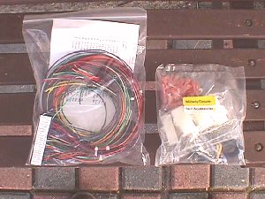
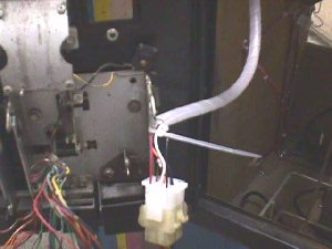
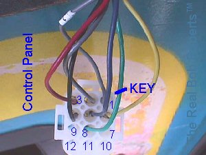
 Did you ever have that feeling that someone was watching you build a Pac game on your lawn in the backyard? I did, so I looked around & sure enough, there was that little fellow that works for Geico Insurance taking it all in. Didn't realize he was a gamer :-) 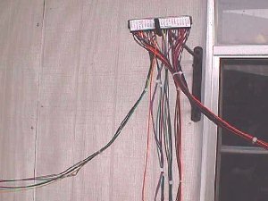 Here's the harness straight from the package & hanging on Alice's plant pot hanger. All the bundles have already been started for you, so all you need to do is finish cable tying each bundle to about one foot from the end. 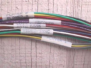 Each bundle is labeled with it's destination making it very easy for you to get them headed in the right direction. 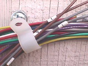 Since colors are repeated on the harness both the coin & start wires are labeled 1 & 2. The reason for labeling both is just a precaution in case one should come off in handling & installation the remaining one would still ID them. 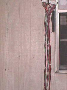 K... cable ties are finished up on all the bundles & it's time to put the harness in the cab. Make sure you put it on with the Parts Side facing out. Then layout each bundle in the direction it needs to go. 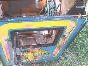 The control panel bundle up to the CP opening, the coin door bundle out through the open coin door, power bundle heading toward the power supply & the easiest one... the speaker bundle working it's way up to the cab top, or wherever you mounted your speaker. 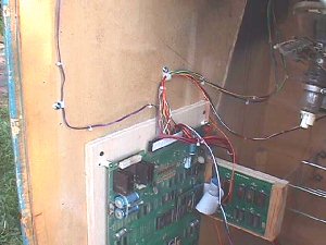 Since it is the easiest one to run I'm going to start with the speaker bundle mapping out a trail for it to follow & cable clamping it as I go. 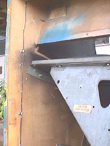 A lot of cable clamps are not necessary... just enough to keep the wires firmly in place, although you can use as many as you want, if that's your personal preference. 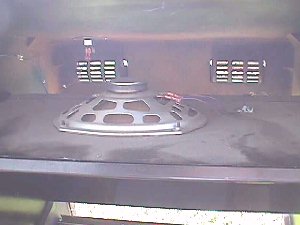 Crimp on the QDs, plug into the speaker & add one last cable clamp to be sure that the wire does not fall back out of reach. 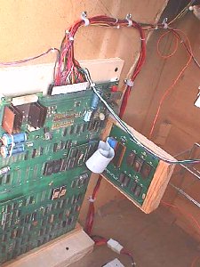 Above I have placed a couple 3/8" cable clamps over the top of the edge connector to hold the bulk of the harness. I pulled the video cable out first as it will simply free hang over to the monitor & I added the mating Molex to the power wires and clamped them in place. 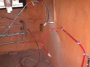 The video bundle & the isolated monitor feed are shown above free hanging in the general area that they are needed. There isn't a chassis on this monitor, but it's now ready to accept one. In the pic below you can see that I have measured & cut the control panel bundle where I want the break plug to be, but I have pulled it through the coin door for ease in stripping the wires back & adding the connector before cable clamping it to the cab wall in the control panel area where it will be needed. Note: Be sure to remark at least one of the gray start lines before cutting, so that you can tell which is start 1 & start 2. If you forget it's easy enough to check continuity from one back to the edge connector to identify them. 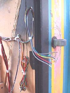 Another thing you can see in the pic above is the bundle that is simply clamped to the wall. This is the player 2 bundle that is only used in the cocktail table along with the single orange wire that comes from position R on the edge connector. This orange wire is for cocktail table use only & when grounded makes the pic flip upside down for player 2. If you ground it in an upright cab player 2 will have to hang from the ceiling to play :-( 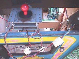 When pinning this control panel break plug you should do so in a manner that will allow you to plug any Ms Pac OEM control panel into it & be fully operational. The Amp connector positions are numbered, but it takes a magnifying glass to read them unless you know the key. I'm going to make up a key read here & give you pin assignments with my harness colors. I'll use a 9 position for the key, but the sequence will continue for 12 or 15 pos. 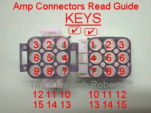
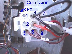
 Pinning the coin door should be done the same way for retrofitting to any Ms Pac coin door. A short piece of black wire will be needed to jumper from pin 4 to pin 7 in order to ground both positions.
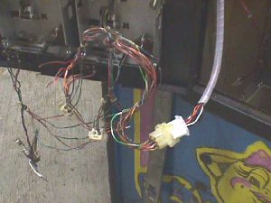
 Here I've added the protective spiral wrap to encase the coin bundle, harboring it from the mighty jaws of the coin door when being opened & closed. 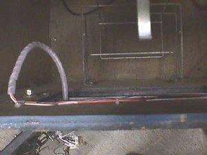 There are several ways of bridging this gap... the connector can be on the coin door & cable tied to the coin mech holder, it can be on the inside wall of the cab with the spiral wrap on the section from the coin door out to the mating plug or you can run straight thru with no break plug. The ideal way is to locate the break plugs as they are in the OEM cab, so that there is never a problem with replacing one section from a dedicated Ms Pac... even if it's only plugging in a control panel from another Pac for test purposes. You can stick build your harness in the cab... meaning run your wires as far as where you need your break plug, cutting them & then continuing on from the mating receptacle... or you can wire it straight through to completion & then go back & cut & install your break plug connectors where they are needed. Some newbies seem to prefer the latter because they can cut, locate the connector position & complete it thru the connector one color at a time. I guess this is less confusing to some, but I prefer to stick build as I go. Of course, I suppose if you're pressed for time or simply want the lazy way out, you could wire everything direct & add in a break plug as needed in the future, say when you need to remove the control panel completely :-() Speaking of pressed for time... I only have a few hours more before Memorial Day (my target for completing this doc) is over & I have 57 of your parts orders to get pulled & packaged for shipping tomorrow, so I'm not going to wire a new control panel or coin door here. I'll leave it with the OEM rat nests that are hooked to both in the pics above and maybe the next holiday will afford me an opportunity to demostrate a neater way to wire both items. Alice says that a closeup of the two finished Amp connectors may be helpful, so I've snapped a couple & added them here.
Next Chapter... Hmmmmm ...Happy Gaming... | ||||||||||||||||||||||||||||||||||||||||||||||||||||||||||||||||||||||||||||||||||||||||||||||||||||