HOW TO BUILD YOUR OWN STAR WARS YOKE FROM EASY TO FIND MATERIALS
By Menace
Thanks extended to:
Civic83 (first proof+gears)
Tiger-heli (second+third+… proof)
1up (render)
xiaou2 (tips)
brax (measurements of Atari yoke)
mahuti (overlay graphic)
Note: A word version of this document (for easy printing) is available here.
Like any project you want to make sure you have all the necessary tidbits before you start and to keep all those safety lessons you learned in high school shop in mind! May the Force be with you! (obligatory star wars quote #1)
Tools I used (not necessarily required but it will make your life easier)
-Drill press with 7/32” bit and 13/32” and 5/16” bit
-1/2” bit (if using Radio-Shack thumb buttons)
-cordless drill
-tablesaw/jigsaw/skil-saw (use whatever one you have—the cuts are fairly minor)
-good epoxy to bond wood to plastic
-sand paper (100 grit)
-wood glue
-protractor/pencil/ruler
-wood clamps
-soldering iron/solder
-dremel with cutting bit and small grinding bit
-hot glue gun
-sound track from original 3 movies (optional)
Materials list:
-1 MS sidewinder (Dual Strike for USB version, or standard for gameport) (optional, this could also be connected directly to the gameport using an old joystick cable and wiring tips from http://www.gunpowder.freeserve.co.uk/wheels/wiring.htm,
or to USB using Daveb’s analog interface when it is
available).
-Sheet metal (15cm x 30cm)
-#6 x ½” round head screws
-#6 x ¾” flat head screws (you could use just one type of screw here but I had both approx. 15-20 required.)
-9” threaded lamp rod with 3 extra accessories package (need a lot of those nuts) (package of 2x12” rods with special fixtures can be found at home depot)
-4” threaded lamp rod (this will need to be cut from larger stock)
-(Qty 2) – children’s spinning hand-held light thing-a-majigs
-regular 2x4 (only need 6” or so)
-1/2” ply wood (need about 9 sq. feet)
-3” x 3” lazy-susan bearing (home depot)
-(Qty 2) leaf spring switches (Ref. Fig. B) or microswitches (your preference) (required for thumb buttons, (Qty 2) Radio Shack pushbuttons, P/N 275-646, $2.29 each, http://www.radioshack.com/product.asp?catalog%5Fname=CTLG&product%5Fid=275-646 (or alternate) could be used in place of the leaf spring switches )
-(Qty 3)- 1” aluminum cotter pins
-(Qty 2) - 1” aluminum fender washer with center hole same diameter as lamp rod
-(Qty 2 each) 40 tooth gear, 20 tooth gear (available from your local hobby shop) (Ref. Fig. A)
-1 7/8” x 1 7/8” project board from radio shack (Ref. Fig. C)
-(Qty 2) 3/4”x3/4” L-bracket (Ref. Fig. C)
(-Qty 2) (5 ½”-8”) plate hangers (from local building supply place—just want the springs J) (optional - substitute Qty 4 springs of appropriate thickness from hardware or auto parts store) (Ref. Fig. E)
-(Qty 2) 270 degree 5K linear pots (the sturdier the construction the better) (substitute 100K pots if wiring to the gameport (not using Dual Strike)) (Ref. Fig. D)
-Lamp rod nuts (4 on Y-Axis (2 on wedges, 2 on gear) 4 on X axis (2
on yoke front, 2 on gear), lock washer for lamp rod (Qty. 6), barrel nut and washer,.
-Small bolt and nut for attaching hobby board to L bracket.
-(Qty 3) 18” strands of 20 gauge or higher (thinner) wire (different colors preferably)
-(Qty 4) 24” strands of 20 gauge or higher (thinner) wire (different colors preferably)
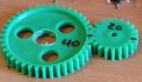
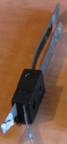
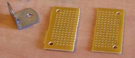
Fig. A Fig. B Fig. C
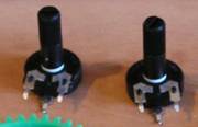
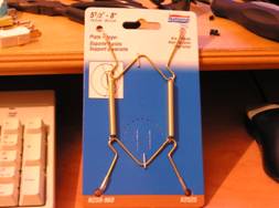
Fig. D Fig. E
Definitions
X-axis - side to side rotation, turning the whole yoke on the lazy susan bearing
Y-axis - up and down rotation, turning the grips on the horizontal
lamp rod
Step 1—Cutting the parts
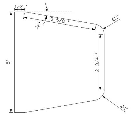
yoke side (2 req’d) (Fig. F)
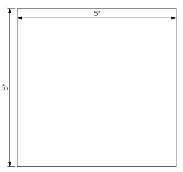
backing plates (2 req’d) (Fig. G)
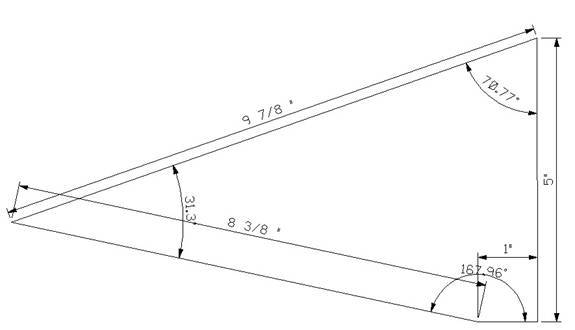
My yoke base (change to suit your control panel) (2 req’d) (Fig. H)
Using these drawings, cut out the two base side pieces as well as the backing plate, the yoke sides and the yoke backing plate. Please note that the size and shape of the mounting base is custom for my machine but can be changed/altered/hacked to suit your cab very easily—with the exception of the front clearance it has nothing to do with the function of the yoke. Also make sure that when you cut the yoke sides and the base sides you have the good side of the wood facing out on each side—this will make for easier finishing after assembly.
With your two -5”x5” (backing plates) mark the exact center and drill a 13/32” hole through both pieces of wood. This is where your x-axis shaft will go so the closer you get to center the better. Therefore, it’s best to clamp the two pieces together and drill them at the same time. With the yoke sides drill a 13/32” hole (or larger if you are using bushings as suggested on the board posting) at 5.5cm from the back of the board and 5.5cm down (these measurements put you in the center of the piece so measuring from any edge will do).
Now take your base sides and bond them to each side of the backing plate using wood glue so that the backing plate is sandwiched in between the side plates (Ref. Fig. I):
NOTE: (You’ll notice that I used 1/8” laminated wood—this was taken from an old TV set that kindly donated its case to the MAME project. I mitered these cuts to keep the laminate continuous. You’d never find this stuff in the wild so the plans were adjusted for 1/2” ply.).
(Fig. I)
Ensure corners are square, clamp the whole assemble, and let it sit for a while. When it’s dried you can screw two 3/4” flat head screws (one at top and bottom) through the sides and into the backing plate, countersinking them so you can wood fill over them later. Now lay the partially assembled base on your remaining ply and trace it’s outline—this will be the bottom—fasten with braces and glue as described earlier (chances are your base will be of different proportions than mine with the exception of the backing plate)
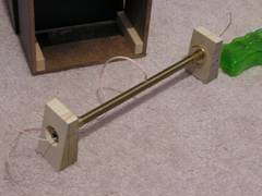
Now dealing with the front half of the yoke, clamp the two side pieces together and find a spot half way down and half way forward, then drill another 13/32” hole similar to what you did for the backing plates. Assemble the front half of the yoke like you did the base, glued and screwed, and you should be all set when that dries--
(ignore the bearings, shaft etc—that’s for later) (Fig. J)
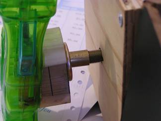
Step 2—preparing the hollow lamp lamp tube for tension springs
I found that the only way to attach a spring to the X and Y axis was to drill holes through the shafts and insert cotter pins. The springs will be attached to the eye of the cotter pin and the pin pushed through the hole. For the Y axis (the one the handles are on) the tube was inserted into the yoke front and centered. I then marked the tube on the inside face of the yoke front side on each side. Using this mark, move towards the center of the shaft 1/16” then drill a 1/8” hole through the center of the tube all the way through—repeat for both sides. This will give you 1/8” of lateral play but your pins and springs won’t bind on the insides of your yoke. You could also insert a washer here. (Pictures don’t reflect this change so you can see the gouges I put in the inside from my first attempt.) Check to make sure your cotter pin fits.
Now take the 4” tube and drill another 1/8” hole approximately 1 7/8” from one end. Attach this 4” tube to the yoke front with the use of the supplied nuts and lock-washers so that 1/2” protrudes from the front of the yoke front. Ensure that the 2 1/8” end of the tube faces towards the yoke front so that 1/8” hole is exposed in the base when assembled. Make sure those nuts are REALLY on there, you don’t want them to wiggle loose over time (maybe a picture would make this easier…) (Ref. Fig. K)
(Fig. K)
 At this point you should also strip the ends of a 5” length
of black wire and sandwich one end between the nut and the large washer plate. This is your main ground/common for the controls in
the front half so make sure it’s tight.
At this point you should also strip the ends of a 5” length
of black wire and sandwich one end between the nut and the large washer plate. This is your main ground/common for the controls in
the front half so make sure it’s tight.
NOTE:
Typically I would like to wire the grounds separately for greater control in the interface
but space inside the lamp tube does not permit this.
NOTE: you could use eye screws instead of the cotter pins but I didn’t have any handy so this is what I used—I may still switch to the eye screws depending on performance—the springs slightly creak with the cotter pins as they move around when the handles rotate—I may also go to a rubber band (elastic for the canucks) approach if this bothers me enough.
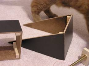
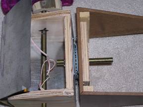
Step 3—The
tricky part, mounting the Lazy Susan Bearing, refer to 2 pictures above
Time to mount that 3” square lazy susan bearing: Position the bearing on the yoke base plate (you should have a hole right in the middle), trace around it, mark and pilot the mounting holes and attach using four 1/2” screws. (This is done to pre-thread the base for easier attachment later.)
Now, remove the bearing from the base, and slide it over the threaded rod and onto the yoke front part, place the bearing in the exact center of the front backing plate and trace all around it. Now, WORKING WITH THE FRONT ONLY, drill a pilot hole for the screw holes in each corner and using your 1/2” screws secure it to the backing plate. Now (leaving the screws in) rotate the bearing 45 degrees and either mark or pilot drill a hole through each corner. You should have 4 holes (marks) offset 45 degrees from the bearing base plate that is screwed in. Now rotate the bearing back so both halves are square and your additional holes are exposed, and drill them out large enough so that the entire screw can pass right through them (5/16” should do).
Now, slide the yoke front assembly into place in front of the base, rotate the yoke front assembly 45 degrees to line up the oversized holes with the pre-threaded holes in the base, and secure the bearing/yoke front assembly to the base using four 1/2” screws.
You should now have a free spinning yoke front that is removable at any time (above pic.)
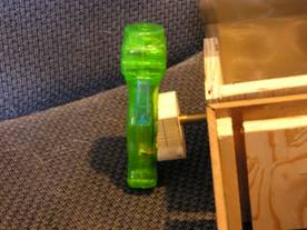
Step 4 –Prepping the handles
Rather than try to describe the thing-a-majigs, I’ll post a pic—
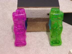 Fig. L
 They started life as one of those kid’s toys that spin and
light up. They had three “tentacles”
with lights in them that spun around when you pull the trigger—you see kids at
fireworks displays, Six Flags, Disney, etc. with them all the time. Anyways, I picked up two at the local dollar store
for 1.75$ and gutted them, leaving only the trigger mechanism intact. They are nice to use because they are generic
handles—no right, no left—so you can use two identical handles for both sides. They also have a slight pistol grip and the trigger
is a rugged little leaf spring.
They started life as one of those kid’s toys that spin and
light up. They had three “tentacles”
with lights in them that spun around when you pull the trigger—you see kids at
fireworks displays, Six Flags, Disney, etc. with them all the time. Anyways, I picked up two at the local dollar store
for 1.75$ and gutted them, leaving only the trigger mechanism intact. They are nice to use because they are generic
handles—no right, no left—so you can use two identical handles for both sides. They also have a slight pistol grip and the trigger
is a rugged little leaf spring.
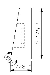
Now using your 2”x4” (or other material 1 ½” deep) cut two wedges using the drawing here (Ref Fig. M.). The larger dotted line indicates where you should bore a hole large enough to accommodate your lamp tube nuts (the smaller dotted lines-pic below (Fig. M)):
(Fig. M)
Drill a 13/32” hole all the way through the exact center of the wedges and then bore your larger diameter hole as shown. Make sure that the wedges have the angled face, facing outwards. Insert the 9” long lamp rod through the wedge from the vertical face side and put the nut on the end so that it is threaded on just flush with the end of the 9” rod—this will keep it centered in the hole. Take a 6” length of black wire and bare the last 3/4” or so—you want to be able to wrap bare wire around the 9” rod. Now sandwich the bare wire between the wood and the nut. This is our trigger ground wire. You might want to thread another nut on the other side of the wedge to keep the wire in compression while we do the next step.
VERY CAREFULLY epoxy the nut to the block, making sure you don’t get any on the lamp tube—makes it very difficult to get undone. Repeat with the other side. When done you should have 2 wedges (mirror opposites) with a lamp nut epoxied to the block.
 Using a drill press, hammer and a punch, lightsaber,
or whatever, drill a 1/4” hole in one side into the center of the threaded rod (Ref.
Fig. N)—this is where the wires will come out of the tube and into your yoke
body—grind any burs. Do not assemble your
sides and shaft yet—picture is for illustration of the center hole only.
Using a drill press, hammer and a punch, lightsaber,
or whatever, drill a 1/4” hole in one side into the center of the threaded rod (Ref.
Fig. N)—this is where the wires will come out of the tube and into your yoke
body—grind any burs. Do not assemble your
sides and shaft yet—picture is for illustration of the center hole only.
(Fig. N)
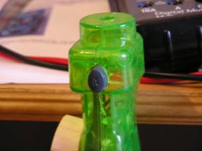
Position the wedge where it feels most comfortable (and is symmetric from side to side) and mark the plastic where the hole in the wedge is. Drill a ¼” hole. This is where your wires will be coming out of the handle and into the tube.
Adding The Thumb
Buttons
NOTE: It is also possible to use a Radio Shack pushbutton as an alternate to the method shown below. However, you will not be able to use the nut to hold the button in place since you will not have access to the back of the button with the handle assemble. If using this method, drill a 1/2” hole at the desired location at the rear (front?) of the handles. You will want to complete the wiring of the thumb buttons, solder wires to the Radio Shack pushbutton and route the wiring through the handle and out the wedge, assemble and paint the handles, then apply epoxy to the Radio Shack pushbutton, and glue it into the hole. (see Tiger-Heli for more details if this is how you go)
This is the method that was used on the prototype:
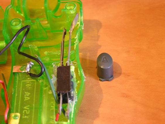
Since you have a dual strike in your possession and it’s going to die an honorable death, we might as well use as many parts as we can from it. I chose buttons A and B from the dual strike as my thumb buttons. To make your life easier you can also use a round button (see Note above) but it has to be able to stay fixed in the plastic while at the same time being able to be depressed and spring back.
First things first, place the button on the back of the assembled grip in the center of the top flat section and turn it over (so it’s right side up but the back of the button faces out) then score a mark all the way around it. Then drill a 3/8” hole approximately 1/16” from the bottom of your scoring job. Next, drill a 1/4” hole slightly above that one. Finally, taking your Dremel and a fine grinding bit, work the opening so that it matches that of the button—(it’s sort of egg-shaped, but with a little massaging you should be able to get it in there without too much trouble. (Ref. Fig. O)
 You’ll notice that the spacing is large enough to accommodate
the button, but not so large as to let the tabs that are at the back of the buttons
through—TAKE YOUR TIME AND DO BABY STEPS WITH THE GRINDING.
You’ll notice that the spacing is large enough to accommodate
the button, but not so large as to let the tabs that are at the back of the buttons
through—TAKE YOUR TIME AND DO BABY STEPS WITH THE GRINDING.
(Fig. O)
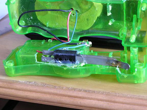
Now we want to attach a leaf spring so that when you press the button, Darth Vader doesn’t start laughing at your impotent weapons…
I used a standard Wico leaf spring (see parts area above) salvaged from an old machine, mainly because I had them and they are readily available to guys like us who likely have reams of this stuff in the basement…Anyways, open the handle and lay the spring inside—if you line the corner of the leaf spring on its side with the corner of the battery compartment on the handle, it makes an excellent spot (Ref. Fig. P and Q). Now mark the edges of the leaf spring and cut away the plastic in the handle, until it’s flush with the handle’s outside edge. Your spring should extend up to about half way through the button—if it doesn’t, adjust its placement so it does—this spring will be your button’s recoil so it needs to have a good placement. Glue the spring in with epoxy or hot glue and let it sit until it hardens.
Feed the ground wire (from the wedge) through the side of the handle and solder it to one of the two handle terminals—it doesn’t matter which—and from there to one of the two terminals of the leaf switch. Now take another length of wire 24” or longer (preferable not black) and solder one end to the other terminal of the handle trigger and feed it back out through the wedge. Solder a third 24” section of wire (different color than the previous wire if you can do it) to the remaining terminal of the leaf switch and feed it again out through the wedge. Now re-install the two handle halves.
Another view: (Fig. P- top) (Fig. Q –below)
Using a belt sander or hand sander, sand down the corners of the wedges until they are smooth and well rounded. Also, sand down the mating face of the handle to remove any bumps. Now epoxy the two together—you’ll have to tuck the ground wire back down through the nut but no big deal. This step involves a lot of comfort fitting—make sure you like how the handle feels in your hand and mark this position before epoxying them together—once it’s together that’s it. Also, make sure you pick symmetrical locations for the right and left grips so your yoke is not lopsided. Here’s my right and left handles (Ref. Fig. R). My thumb fits nicely over the wood block, completing the pistol grip feel.
(Fig. R)
AT THIS POINT, YOU CAN PAINT YOUR HANDLES, BUTTONS, BASE, AND YOKE WHATEVER COLOR YOU FEEL LIKE—I WILL BE FINISHING THESE WITH A NICE GLOSS BLACK “PLASTIC FRIENDLY” PAINT WITH THE BUTTONS BEING A GLOSSY RED.
Step 5 –Pots, gears and springs
Using your drill, make a 13/32” hole through the exact center of both 40 tooth gears. Now make a hole through the center of the 20 tooth gears to exactly match the diameter of your pot shaft—the goal is to be tight here. Attach the 20 tooth gear to the pot. If it’s a loose fit, glue it into place.
Taking your 1 7/8” square hobby board from radio shack (Fig. C), cut it in half
and drill a 1/8” hole approximately 1/2” from one edge and using a small bolt
and nut, affix the ‘L’ bracket to the section of hobby board (see Fig. S). Trim the hobby board so that when 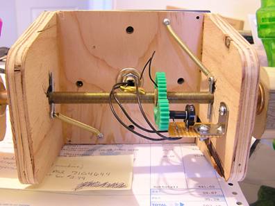 the 20 tooth gear is attached to the
pot, there is clearance. (Depending on your
pot design, yours may look different than mine) . Now, solder the pot to the board and set aside.
the 20 tooth gear is attached to the
pot, there is clearance. (Depending on your
pot design, yours may look different than mine) . Now, solder the pot to the board and set aside.
(Fig. S)
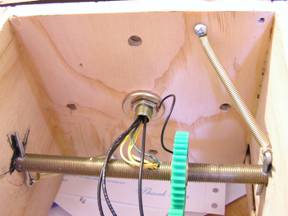
Insert your 9” threaded tube through the yoke front sides. (Ref. Fig. S). Make sure to thread on a fender washer (not shown), nut, a lock washer, the 40 tooth gear, another lock washer, another nut, and another fender washer (in that order) as you push it through. (The fender washers will go outside of the cotter pins to keep them from digging into the wood). Taking your cotter pins, push a spring onto each until it makes it to the loop—try not to deform your cotter pin since this will make inserting it through the hole more difficult. Push one cotter pin through right side up and the other upside down (see above) and bend their legs so they don’t slide out. Screw the other end of the spring to the backing plate so that there is some tension in the spring—move laterally if necessary. Now carefully screw in the other spring so the tension is balanced.
Now position your 20 tooth/pot / ‘L’ bracket combo and mount it to the inside wall of the yoke (use the 40 tooth gear as a guide to where this gets mounted). Try to center the pot as much as possible at this point (so there is as much of 135 degrees of rotation as possible in either direction). Now position your 40 tooth gear in line with the 20 tooth and thread the nuts so they pinch the large gear in place—again get them tight. Remember that ground/common wire that’s attached to the back and just dangling around? Pinch it between a washer and the nut on one side of the 40 tooth gear—you should have plenty of slack for a 60 degree rotation.
Flip the yoke over and solder three wires (roughly 18” long) to the pot legs. Feed the other end of these wires through the 4” rod at the back.
Now repeat those steps with the base, modifying slightly for your shape and area. Here’s mine (here’s where a cotter pin is definitely going to be replaced—the springs creak like crazy so I had to put some cinch ties to hold them in place—not very elegant but they don’t creak anymore)
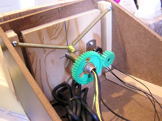
(Fig. T)
Attach another ground/common wire to the outside washer/nut on the center shaft (not seen in photo) similar to what you did on the inside. This will eventually be connected to your Sidewinder.
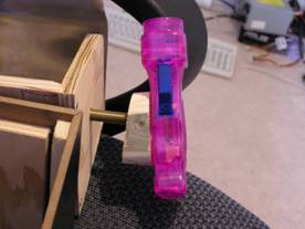
Step 6 Attaching the Handles
Your handles should have two different colored wires protruding-one for each button. Feed this through the hollow tube until you can see it in your center hole—using a pair of needle nose pliers or tweezers, pluck the wire out of there and feed it through the 4” tube at the back—repeat with both sides. You may have to give it a few tries since your cotter pins are in there, but it will go eventually. Also feed the three wires from the Y-axis pot through the 4” tube. You should now have seven wires coming out of the back of your yoke, with another three coming from the 5k pot at the back.
Thread on the large spacer nut and a flat bearing plate and then your handle. Your handle should have a good 3 or 4 turns before you feel some resistance (i.e. you’re threading into the side of the handle) back it off until the handle is in an upright position. Then cinch the barrel nut and washer into place—again, really tight. (Ref. Fig. U). Repeat for other side.
 (Fig. U)
Step 7 – Wiring
The beauty of the sidewinder is that others have gone the path before us, making our work that much easier. 1up from www.1uparcade.com kindly donated this render to illustrate the wiring. (Ref. Fig. V)
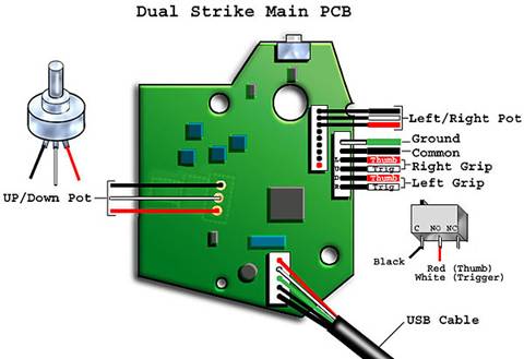
(Fig. V)
When you get it all started and you are in windows you may notice that your directions
are reversed. Have a look at the offending pot
(the one that’s reversed directions) and switch the left and right wires—leave
the center one alone.
Step 9 –Covering It All Up
Before you cover up all your hard
work—double check all your nuts and make sure they are tight, plug the beasty in and calibrate it using the joystick setting on the
sidewinder—some of the pots may need a tweak left or right to center. When all is as it should be, use some hot glue or
epoxy and put a dab on all the parts that conceivably wiggle loose. This would be all the nuts visible inside (at the
gears, circuit board, backing plate etc.).
Using your sheet of sheet metal start at one of the back edges of the yoke front and using finishing nails (with a larger head) tack the sheet metal into place—use a lot and make sure the metal is tight as you go around the corners—don’t worry, it’s all going to be covered. It’s also easy to take off if you ever have the need to upgrade or repair your yoke, but won’t come off accidentally. Make sure there are no sharp edges protruding and file/grind them down if there are.
With the base section, cut a piece of ply to cover this area and bolt/screw it
down—I would recommend against gluing, just in case your pot dies or a spring
breaks—How you do this is up to you—some may like the look of finished round
bolt heads, or some may like the look of plastic screw head covers—I went with the
black plastic screw head covers—available at home depot for .10 ea..
Step 8-- Artwork and attaching this beauty to
your cab
Artwork for the original yoke can be obtained from www.localarcade.com/4images/ (special thanks to mahuti for the yoke overlay). Using photoshop or illustrator adjust the image to match the dimensions of your yoke and glue to the sheet metal with a spray-on adhesive.
To attach the yoke to my cab I used 5 sucker cups that I had scavenged from another joystick using #10-32x3/4” flat head machine screws, I drilled out the center of each sucker cup and fastened them to the underside of the yoke (Ref. Fig. W)
You could also make a threaded connection similar to what 1up did so I would refer you to his site if this is the course you’ve chosen.
(Fig. W)
A yoke you now have, fight the empire you must, may the force be with you…..cue music….
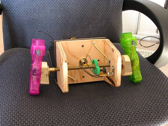
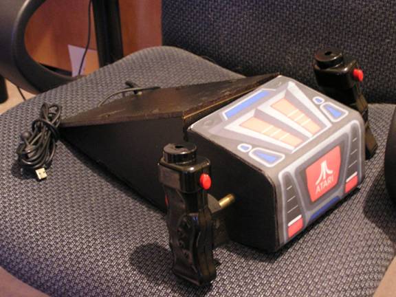
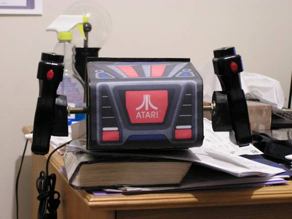
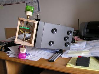
Completed Assembly
Here are some pics of the finished yoke: