![]()
 |
|
| Original writeup | Modified project |
![]()
Brian sent me his arcade joystick project and asked me to share it with everyone. Two joysticks, trackball, and the first build-your-own spinner from Twistygrip that I've seen. Another project where the more I built this page, the more I went "wow, this is really cool" :) Thanks Brian!
LEARNING
I've capitalized this first step because this is what I did before anything. I looked up a TON of information on how to build arcade cabinets and joysticks from many different sites, including this one. After studying those projects for a while I decided I had enough knowledge to start building my own joystick. I eventually want to build the whole cabinet, but I don't have the space I need to do that just yet.
Interface
After the info part, I needed to decide how I was going to interface the joystick to the computer. I had read all the info in keyboard hacks, Hagstrom encoders, and joystick hacks and I decided that I was going to go with the keyboard hack for two reasons. First I could get the old keyboard from a guy I worked with who was going to throw it away anyway so it was FREE and second it was cheap (going back to the FREE part.) I just couldn't see spending $100 for an encoder when most of the older games that I was making this for could work well enough with the keyboard hack.
Starting the Project
(Click me for a larger view)
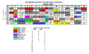
Keyboard Matrix
(Click the picture for a larger view in html, or choose the original Excel spreadsheet which is better. --saint)
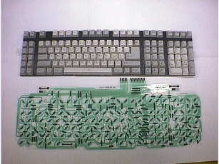
After taking apart the keyboard, I needed to start mapping out the matrix so I could assign the buttons to the keys while minimizing the ghosting problem. My particular keyboard matrix can be seen here. I used a tip that I had read about on this site to make the mapping process easier. I started tracing all keys by hand on the PCB, but that was taking forever. Then I read about using a multimeter to make the connections from the mylar to the PCB. This worked great and I knew all the keys were correct since I wasn't relying on just my eyes.
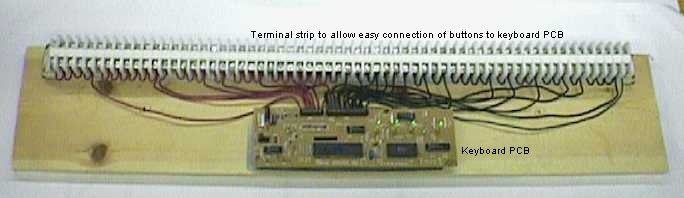
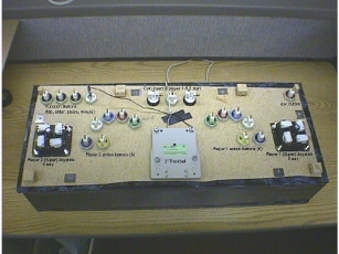
Mounting the Keyboard PCB
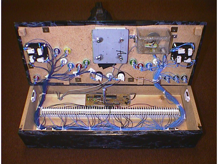
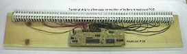
After mapping out the matrix, I then proceeded to solder all the wires to the PCB which would eventually be connected to
terminal blocks. A word of caution here, take your time and check each solder connection with the multimeter so that you don't accidentally connect to the lead next to the one you just soldered. If this happens you could fry your PCB or your
motherboard. After soldering the wire to the PCB, I decided to mount my keyboard PCB to a piece of pine along with a din rail and terminal blocks. I used the metal mounting plate that the PCB was originally mounted in the keyboard case to mount it to the wood so it was really easy. All I had to do was cut the metal down a little and drill mounting holes through it and I was ready to fasten it to the wood. The reason I decided to mount the PCB to the separate pine rather than the joystick box in case I ever wanted to change the location of the PCB in my cabinet someday when I build one. I used the terminal blocks so I could easily make button changes if needed and not worry about soldering wires. It works great! Here's the PCB and terminal blocks mounted to the wood.
(Click me for a larger view)
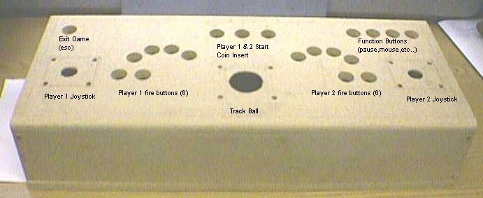
Control Layout
Now that the hard part was done I had to figure out what layout I wanted for the joystick. I looked at many, many layouts and I finally decided to go with a layout that fit my hands while I was standing and sitting them on a flat surface. I wanted two joysticks and 6 buttons per player. I used a layout that made it so player one would move the joystick with their left hand and fire with their right. I did this because that is what I like when I play games, but you might prefer something different. Player two uses their right hand for the joystick. This also helps space out the players too so it's not too crowded. I also wanted a trackball so I decided to put that in the middle and have the escape and other function buttons on the top of the joystick.
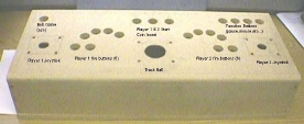
(Click me for a larger view)A quick tip for layouts, use a piece of cardboard to test layouts and find one you like, then trace the button positions onto the board and cut them out. I went through about three different layouts before I decided on the one I'm using.
Joystick top construction:
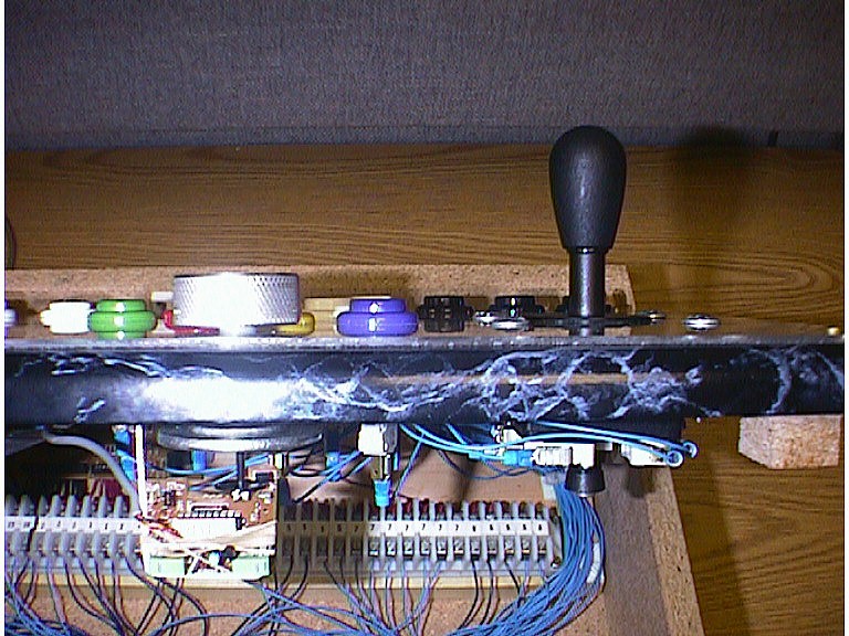
The next thing I did was to cut out all the holes for my joysticks, trackball and buttons. You already saw the layout in the above picture since I threw away my cardboard before I thought to take the picture. I used a 1 1/8" hole saw to make all the holes and used a router for the trackball hole. I also routered out the joystick areas so they would stick up more since I was using ¾ inch particleboard. I don't like short joysticks. I also routered the trackball area so more of it would stick out of the wood. Here's a shot of the routered underside with the controls installed.
(Click me for a larger view)
Box Construction
After cutting out the holes for the controls in the top, I then had to construct the main box. I wanted to make it a totally enclosed unit since I wasn't going to put it directly on a cabinet yet. The design of the main box was simple. It was a 30" long x 12" deep box with wood screws holding it together. I used magnetic latches for cabinets to hold the top down more securely onto the main box. I also put square pieces of wood in the corners so that the top wouldn't move. Both of those things help make it a sound joystick when really hammering on the controls while making it easy to remove the top if I need to work inside. I didn't make the top slant at all like some joysticks since I'm kinda tall and when I'm at the arcade, my wrists cramp up because they are at a sharp angle because the control panel is angled. If I was shorter, I might have angled it, but I'm not so I didn't.
Controls
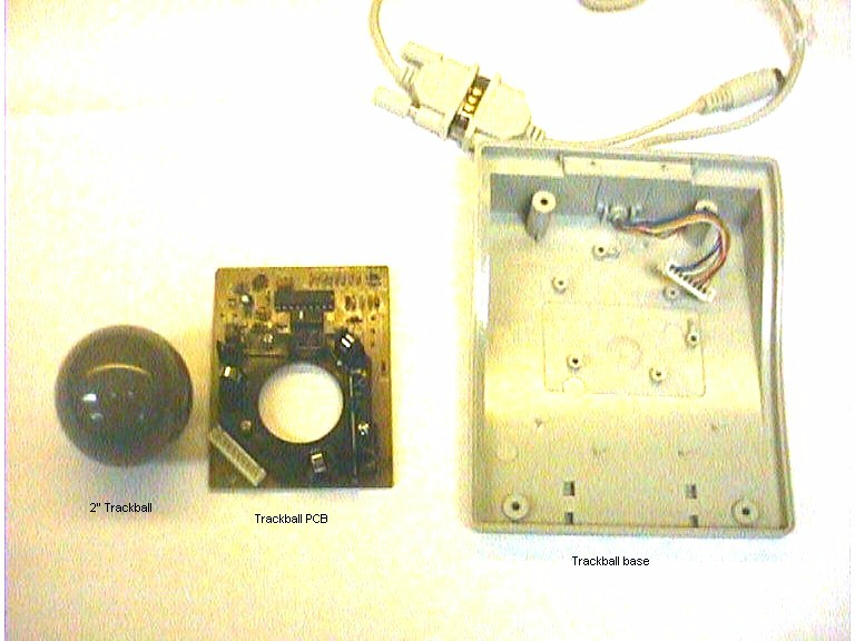
I decided to go with two 8 way Happs Super joysticks with 6 Happs competition pushbuttons per person. For the trackball I bought a digital research 2" trackball at Best Buy. In my initial design I didn't have a spinner included, but I later used the build your own spinner instructions from Twisty Grip to build my spinner and added that on after the joystick was done which you can see in this picture.

(Click me for a larger view)
Trackball
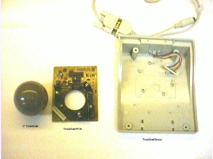
(Click me for a larger view)
Spinner

(Click me for a larger view)
Finishing touches
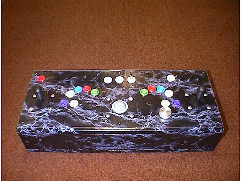
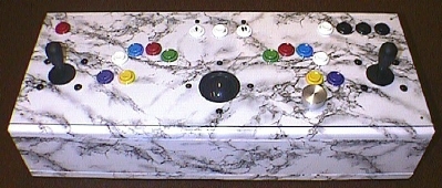
To finish the joystick off, I put blue marble contact paper on the top and front. I didn't put any on the sides since I'm going to bolt it to a cabinet someday. I also put a piece of plexi glass on the top to make it look more like a real arcade control panel. Also as a neat touch I wired the LEDs for the Num lock and Control lock from the keyboard PCB and put them
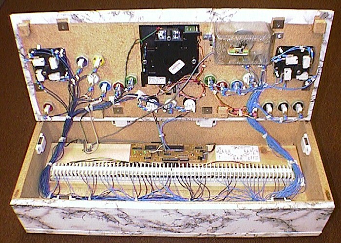
over the player one and two buttons so they flash when you insert coins. It really makes it look authentic. One last thing I did was to put rubber feet on the bottom of the joystick so it doesn't move when you use it. So here it is,
the final product inside and out.
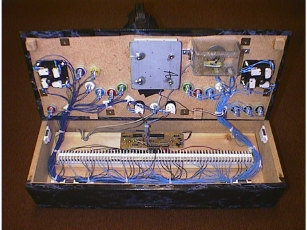
(Click me for a larger view)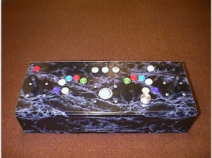
(Click me for a larger view)
COST
This is a pretty important topic. I wanted to keep the cost down and I was lucky because most of the material I used was scrap from work, or hand me downs from other people. The breakdown of cost is like this:and that's about it! So the total is just over $100. Not too bad for what I got and it works great! If you have any questions or want more detailed explanations, e-mail me at bconey@voyager.net GAME ON!!!
- Happs controls $52
- Wood for box $15
- Plexiglass $9
- Spinner $13
- Trackball $25
- Contact paper $5,
The Update!
My Arcade Joystick Modification
OK, I know I said in my previous write-up that I couldn't see spending $160 for a Happ Trackball. Well time has passed and as I used my hacked 2" trackball from Best Buy, I just couldn't hammer on it like the real thing without worrying about damage. Needless to say, I wanted to upgrade to the real thing so I didn't have to worry about damaging the trackball. So with that, the following write-up gives you some information on how I added a 3" trackball to my ¾" thick wood panel, and also a few pictures for clarification.
Ordering the necessary parts and cost
The first thing you need to do, of course, is decide what you want to order. You can order the 2 ¼", 3", or 4 ½" trackball. Luckily I planned ahead a little and allowed enough room for the addition of the 3" Happ trackball. So then I needed to determine what parts I needed from Happ and came up with this list:
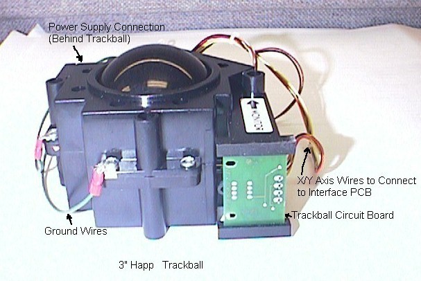
The Happ 3" Trackball
(Standard color black)
$80.00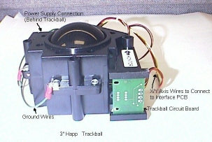
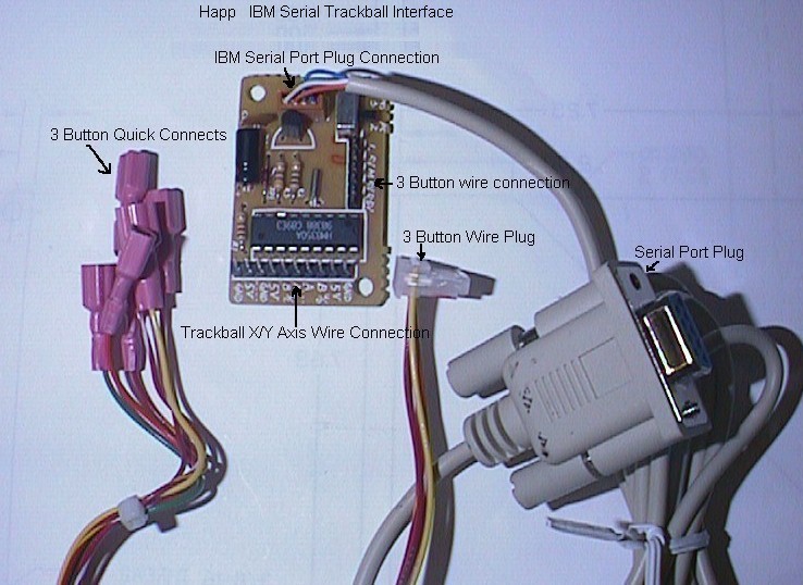
(Click me for a larger view)The Happ IBM Serial
trackball interface kit
$49.95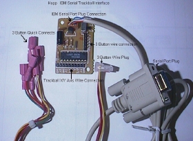
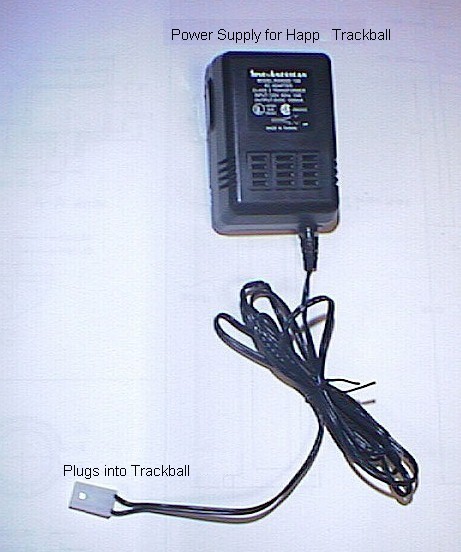
(Click me for a larger view)The Trackball
power supply
$19.00
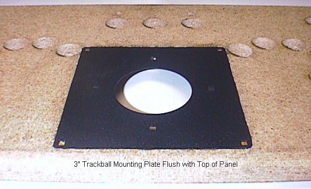
(Click me for a larger view)The black wrinkle
painted trackball
mounting plate
$6.25
(Don't click me :) )Four 3" carriage bolts
used to mount
the trackball
$.20 each
Modifying the control panel top
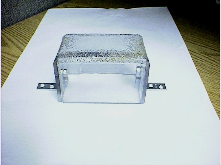
Next I had to decide the best way to mount the trackball to the control panel. I liked the appearance of my panel and I really didn't want to have a big black plate in the middle for the trackball. I wanted to be able to mount the trackball yet still keep the nice look of the marble without the plate. First I used a jigsaw to cut a 5.9" X 5.9" square hole just big enough for the trackball to fit into. Once that was done, I traced the mounting plate and used a router to recess an area just big enough for the plate to fit into. This allowed me to mount the plate flush with the top of the panel . . .
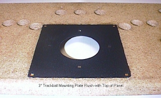
(Click me for a larger view). . . and also allowed me to cover it up later with the contact paper so all that would be showing would be the trackball. I used super glue to hold the plate to the top. You may be thinking that this won't hold, but believe me, it does without any problem. You could use epoxy instead, but this is just what I had around, so I used it.
Recovering the top
Since I already had to take all the controls off the top so I could work on it, I decided I might as well change the color scheme too. The main reason I did this was because I was talking with my wife about what my cabinet should look like when I eventually build it and she said, "why make it look like all the other ones, make it look like a piece of nice furniture. You should make it out of oak." She also mentioned that white marble would look better with oak than what I had, so I decided to take her advice and make the change. I bought some white marble contact paper from Home Depot and put it on the top and front of my panel just like before. It looks great! Thanks Ellyn!
Test fitting the Trackball
After the trackball mounting plate and new contact paper were on the top, I needed to test fit the trackball and make sure everything went together the way it was supposed to. It turns out that the 3" hole in the plate was so tight on the trackball that I had a hard time fitting it into the plate. I needed to increase the size of the opening just BARELY so it would fit easier, but wouldn't be too big. To do this I used a hand grinder and very lightly went around the diameter of the circle in the plate. I did this until the trackball fit easily into the plate. If you do this, just take your time so you don't remove too much material. You can always take more, but you can't put any back.
New Polycarbonate for the top
Since I was changing the layout of the top, my old plexiglass wasn't going to work anymore, unless I wanted holes in it where they weren't supposed to be, and I didn't really want that. This time I used a piece of polycarbonate instead of plexiglass. This stuff is A LOT stronger than plexiglass and is also a lot easier to work with. I cut all the usual button and joystick holes with the 1 1/8" hole saw running backwards to melt through the polycarb and give me good holes. For the trackball hole I did the same thing with a 3" hole saw. For the joystick, trackball, and spinner mounting holes I just used regular drill bits. I was able to do this since the polycarbonate is stronger than the plexiglass. I then filed the trackball hole and sanded it so it wouldn't be sharp when people used it. It worked really well and there aren't any cracks at all!
Mounting the Trackball
Ok, so now all the prep work is finished and all that remains is to actually mount the trackball. For this I used the four 3" long carriage bolts that I ordered from Happ. I just fed them through the mounting holes and used 10-24 lock washers and nuts to hold it to the plate. It's that easy!
Mounting the Interface kit
I also had to mount the interface kit somewhere where it could be reached easily by the trackball wires and not get in the way when I opened the panel. I decided to mount it underneath the top next to the trackball. Here's a shot of the mounted trackball and interface kit from underneath the panel. |
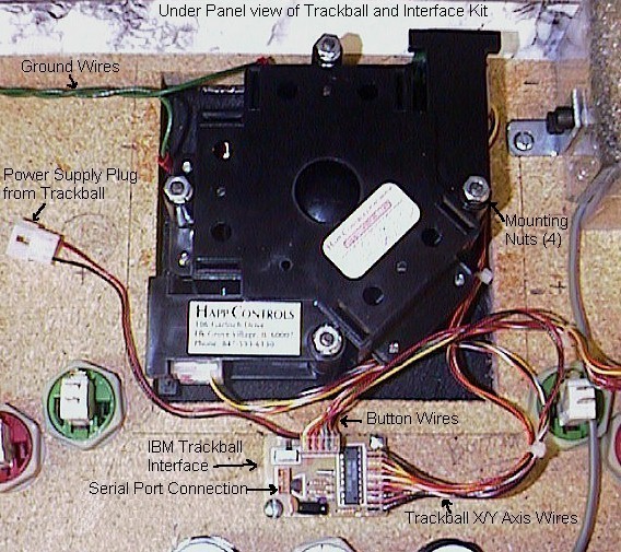
(Click me for a larger view) |
Wiring
After everything is mounted, the next thing that needs to be done is the wiring. When I received the trackball, I noticed that it had two earth ground wires on it. This presented a problem for me since I didn't have a nice place in my panel to attach them. I called Happ Controls tech support and asked them if I needed it. They said that in hot and dry areas, the trackball discharges some static and that I should really use the ground wires. Ok, so I had another problem to solve. What I did was solder a longer wire to the two ground wires and put an alligator clip on the end. This allowed me to run the ground wire out of my panel, down the chord for the keyboard and clip it right to the frame of the computer, which gave me the ground. I'm planning on doing this when I build my cabinet too. Simple yet effective. Next comes hooking the power supply, serial plug, trackball, and buttons to the interface. This is very easy since all you need to do is follow the simple diagram that Happ provided with the interface kit shown here.
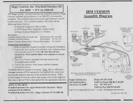
(Click me for a larger view)You will need to switch the wires that come with the trackball to do this, but those are also provided in the kit.
Testing
After all the wiring is finished, it's time to test it out. All you need to do is plug it into your serial port, plug the power supply in, and turn the computer on. It should work right away. One thing to note is that you need to plug in the trackball power supply BEFORE you turn your computer on or the trackball won't work.
Finished Product
So that's it. It really wasn't too hard and didn't take too long ether. I hope this makes it a little easier to install yours or to decide if you want to go this route. Finally, here's a shot inside and out of my new and improved Arcade Control Panel.
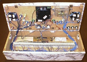
(Click me for a larger view) (Click me for a larger view) Again, if there is anything you would like me to explain in more detail, you can contact me at bconey@voyager.net.
Acknowledgements
I'd like to thank a few people that really helped me out. Without them, this panel wouldn't be as nice as it is or might not even exist. Thanks to Ellyn, my wife, for listening to me go ON and ON about this stuff and for giving me great ideas on how to improve my panel and eventually build a cabinet. My dad for lending me his router, Brent for the keyboard plug, Wayne for giving me his old keyboard and letting me use his router too. Also thanks to Marv and Claude for letting me use their tools and Eddie for helping me out when I was building this thing. Finally, thanks to saint for posting my write-ups and for having this great site! Thanks Everyone!!Game On!!! Brian
Another very impressive project! Thanks Brian!