|
Building an Arcade
Control Panel for your PC
by Greg Bendokus and
Craig Johnston
Version 1.0
This project will allow
you to connect an arcade-style leaf switch, or click switch joystick
to your PC's game port through the use of the guts from a PC game pad.
Yes, you read correctly. To be able to complete this project, you must
be in possession of the following:
-
An arcade joystick, preferably
the whole console with sticks and buttons, right from an arcade machine.
You can also buy authentic arcade joysticks and buttons from companies
who supply the arcade industry. They are very cheap. Buttons are usually
around $2 each, while joysticks are around $??. Here are the ones used
in preparing this document. The joystick is called a Universal joystick,
and can adjust from a 4 way to an 8 way joystick.
-
Some basic knowledge of electronics,
i.e. how to follow circuit board traces and the difference between hot
and ground.
-
One (or 2) PC game pads. What
kind to use it up to you - the $8 ones from CompUSA work as well as a Gravis.
Don't get too fancy because you're going to junk everything except the
circuit board inside (hereafter referred to as the circuit card). This
is one from CompUSA.
-
A spool of wire, available
from Radio Shack, which will be used to connect the leaf switches to the
game pad circuit card. Don't use anything too thick, or you will have problems
with your wire overlapping traces on the circuit card, causing all kinds
of headaches. You will also need a short piece of this wire with both ends
stripped, to use as a test lead.
-
A soldering iron. A good pencil
iron from the Shack will do - just don't use one of those industrial 600
watt guns and you should be fine. Since we'll be soldering directly to
the circuit card, don't use solder with a lot of rosin in it.
-
3 Pieces of wood. I used 1
piece of 1X12 Knotty Pine, and 2 pieces of 1X4 Knotty Pine. Total cost
was $3.33. Nails of course.
-
A drill, with the bit that
can cut round holes. These holes will be for the joystick and buttons.
I used a 13
" (31.8 mm) bit. I found it a little too big, but it still worked.
BUILDING THE BOX (skip
this if you are using a control panel from a real arcade game)
This section will show you
how to build a Stargate/Defender box. Please use your own dimensions if
you want to position the buttons on your own.
-
The piece of 1X12 wood should
be 24.4" (62 cm) in length and about 8" (?? cm) in width. I left the width
as cut by the lumber company, to give me a place to rest my arms. The 2
pieces of 1X4 would be cut to fit on the bottom for support.
-
Now use a pencil and measure
out the position of the buttons and the joystick.
 |
Joystick
- 5.1" (12.9 cm) from the left, and 2.4" (?? Cm) from the top. |
|
Reverse
button - 7.3" (18.5 cm) from the left, and 3.8" (9.7 cm) from the top. |
|
1
Player button - 10.7" (27.15 cm) from the left, and 1.9" (4.7 cm) from
the top. |
|
2
Player button - 10.7" (27.15 cm) from the right, and 1.9" (4.7 cm) from
the top. |
|
Thrust
button - 6.1" (15.5 cm) from the right, and 1.9" (4.7 cm) from the top. |
|
Fire
button - 4.6" (11.75 cm) from the right, and 1.9" (4.7 cm) from the top. |
|
Smart
Bomb button - 7.2" (18.4 cm) from the right, and 3.0" (7.65 cm) from the
top. |
|
Invisio
button (Stargate) - 8.4" (21.25 cm) from the right, and 4.2" (10.65 cm)
from the top. |
|
Hyperspace
button - 11.6" (29.45 cm) from the left, and 1.9" (4.7 cm) from the bottom. |
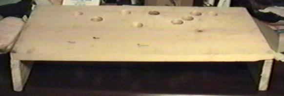
The measurements are to
the center of the buttons. Now, drill the holes, and nail on the support
legs.
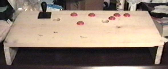
It should look like this
when you are done.
-
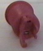
Now unscrew the joystick. It works similar
to a light. You twist, and then pull it apart. You then put the ring on,
and screw on the screw ring to lock it in place. Last, you
screw the base back on.
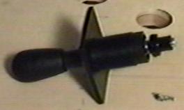 
Joystick top
Joystick base
Joystick ring
Joystick screw ring
-
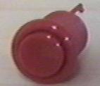
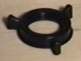
Now the buttons. The are easy.
Just put the button in its hole, and screw on the ring to lock it in place.
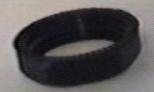
Button
Ring
-
Now mount the buttons and joystick
in their correct places. It should look like this. Please note that I was
missing 2 of the buttons.
-
Now you are ready to wire everything
up.
STEP 1 - Getting Ready
-
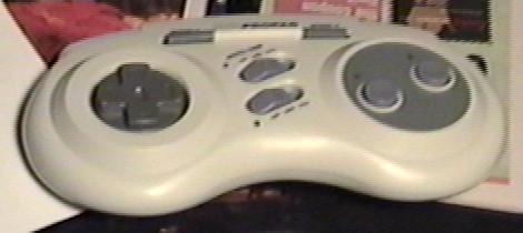
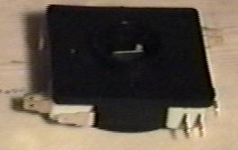
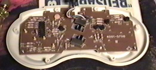
Take your game pad, remove
all the screws, and open it up. Throw away everything except the small
circuit card, attached to which is the cable that plugs into your PC. It
should look like this.
-
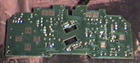
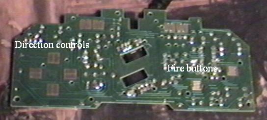
Take out the PC board, and
turn it over. If you have a common game pad, you should see 2 groups of
4 round traces on the circuit card. 4 of these are for the fire buttons,
the other 4 are for the compass directions. Determine which ones are which.
It should look similar to this.
-
Plug this shell of a game pad
into your PC and turn it on.
-
What you need to do now is
to fire up any game program on your PC that has a joystick calibration
function in it. The choice is yours, but make sure the program shows you
the actual position of the joystick on the screen. MsPacPC is a good example.
If you have Windows 95, you can use the joystick setup applet in the control
panel, which is my preferred method. Be sure you have the joystick type
set to "4 button game pad" if you do this.
STEP
2 - Finding the correct traces.
Each round trace on the
game pad card has 2 circuit traces leading to it, usually one on each side.
By connecting a single piece of wire across both of these traces, you "close
the circuit" for that switch and the game pad circuitry thinks you've just
pressed a direction (or a fire button). What you want to do is take your
test wire and manually close these switches and see what direction is registered
in your calibration program. The switches on PC game pads are usually arranged
this way:
Take a piece of paper and
jot down your findings.
Of course, if your arcade
joystick setup is using only 2 fire buttons, you don't need to worry about
buttons 3 and 4. If you are using 2 joysticks (you will need a joystick
"Y" cable, available at the Shack), be aware that your PC is limited to
2 fire buttons each when using 2 sticks.
STEP 3 - Time to do
some soldering.
Well, we're ready to solder.
Look at one of the leaf switches on your arcade stick. Each one should
have 2 solder blades on it, even though some have 3, like Wizard of Wor
sticks. If you have purchased arcade buttons and joysticks, then the micro
switches will have 3 solder blades. The micro switches should look like
this.
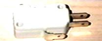
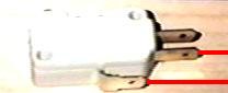
If you look at the side
of the micro switch, you will see a faint diagram. The diagram shows the
position of the switch when not pressed. When you press the switch, the
two solder blades used are the one on top, and the one on side, that is
closest to the top.
All you do now is simply
solder each blade to opposite ends of the traces for that direction on
the game card. Let's do the left direction first. Move your joystick left
and note what leaf switches close; it won't always be the ones you would
think! Now, solder a wire, about 6 inches long, to one of the blades on
the back of the leaf switch. Repeat for the other blade. Now take these
2 wires and solder them, one to each side, to the left game pad direction
trace on the game pad, which you've determined earlier with your test lead.
If you are having trouble soldering to the
Move the joystick left,
and with any kind of luck, the screen should say that you're moving the
joystick to the left. If this works, congratulate yourself and wire up
the rest of the directions and any fire buttons you're using. Repeat the
whole process with another game pad card if you have second joystick.
Some of you may note that
I didn't mention you could tie all the grounds together on the leaf switches
and just run one wire to the low side of all the game pad's switches. I
seem to get better results when I DON'T do this, i.e. the stick calibrates
easier with my software.
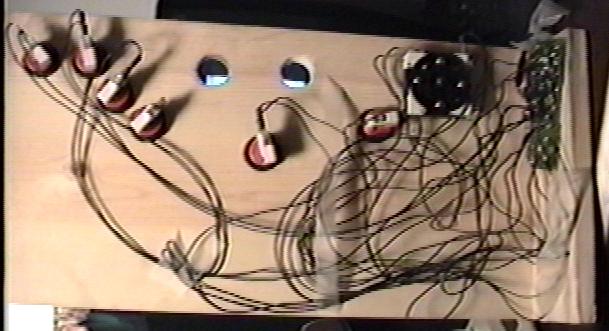
It is also a pain in the
ass to find a common ground on a game pad - it's just easier to make each
connection a separate one. Feel free to experiment, though. This is a messy
picture, showing a completed control panel. The game pad PC board is on
the right.
STEP 4 - Finishing
up.
That wasn't so bad, huh?
Hopefully, when you got your joystick, you also got the wooden enclosure
it came in. If you did, you can use a screw and attach the circuit card
right to the wood next to the joystick assembly. Most game pad circuit
cards have holes in them, which make this easy to do. Just make sure none
of your wires interfere with the leaf switch blades. You can then take
a piece of plywood, cut it to fit the back of the wooden console, and nail
it on, making a box. Use a staple gun to fasten the PC cord(s) to the wood
so your handiwork isn't ripped to shreds if the cord is yanked. You should
now have a completed box with one (or two) cords coming out of the back,
ready to plug into your PC.
Now, plug the thing into
your PC and fire it up! I recommend trying Starforce to really give the
thing a good workout. If you've wired up 2 sticks, the logical choice to
try first would be Robotron (worth building for this game alone). Be sure
to calibrate the program(s) for your new stick(s) first! If all goes well,
you should be quite impressed with your work. It should also become quite
apparent what you've been missing by trying to play these emulators with
a game pad. :-)
POSSIBLE PROBLEMS:
-
You may need to adjust the
gaps of your leaf switches. If you find it hard to move diagonally, check
each individual direction and adjust the switches for the best feel. There
is a very fine line when setting leaf switches - either they don't touch
at all or they are too sensitive. If you have a leaf switch blade adjustment
tool (looks like a knitting needle with a gap on the end), this will be
a much easier process. I have no idea where to get one of these tools -
arcade machine repairmen usually have them.
-
It may be hard to accurately
calibrate the joystick in some programs. The only real problem I've had
is with Mike Cuddy's Gyruss and Time Pilot emulators. The on-screen joystick
cursor just goes nuts when I try to calibrate the stick. I resorted to
plugging in a normal game pad, calibrating the program with that, and then
plugging the arcade stick back in. No problem. Most other programs, like
Sparcade and even Doom(!), calibrate quite easily and work like a champ.
MAME even calibrates automatically, which is really nice.
-
You may be tempted to try to use an Atari
joystick instead of an arcade stick. Don't bother. The 'bubble' switches
on these joystick's circuit cards have such a weak electrical
connection that the end result will always seem to be erratic, with one
direction usually refusing to work at all. Experimenting with this is where
the whole project started, however.
-
I've tried my setup on several
Sound Blaster cards, including one of those $30 clone cards, with no problems
at all. I have NOT tried it with a GUS, or anything else for that matter.
I can't imagine why one sound card's gameport would behave differently
than any other, but in world of computer hardware, anything's possible.
Well, there you have it. If
you run into any problems or just want to tell me how you like your new
controller, please Email us at:
bendokus@postoffice.ptd.net
or craig@humanoidsoftware.com
You are free to upload this
document to whoever or wherever you like, provided you do not modify it
in any way.
I will not be held liable
for any misuse of the information contained herein. What this basically
means is that I am absolved of all blame if you blow up your PC.
I'd like to thank all of
the arcade emulator authors for their hard work, allowing me to re-live
a prized part of my childhood.
Thanks also to Phil for
reading my first draft of this document. Your web page will definitely
be missed!
Finally, special thanks
must go to my good friend Scott Stilphen, arcade machine guru that he is,
who patiently endured my temper tantrums when we first tried to wire up
Atari sticks to a Gravis pad. Without him, this project would have never
happened.
Greg Bendokus
3/19/97
Craig Johnston
7/30/97
|
|