| << DRAWINGS |
![]()
If you do not have experience with a soldering iron I advise you to leave the soldering to someone more experienced. Otherwise, take your soldering iron and solder all connections as shown in the drawings.
DB-25 Connector
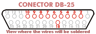
We have already done the most difficult part. All that's left now is making the connections to the DB-25 connector and to make the connections with the female connector on the N64 controller. To the right, we have the image of the connector with the pins that we are going to solder in red.
Connecting the controller to the circuit
 In order to connect the N64 controller to the circuit we have two options: a clean, but
expensive method, and a less clean but free method.
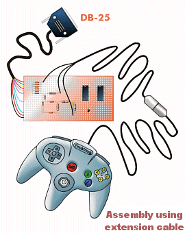
The cleanest method is to buy an extension cable for the N64 controller
($8 at Wal-Mart), cut the cable and wire it
directly to the points of the circuit. It is advisable, before soldering, to
verify with a meter which color wire goes to what holes of the female connector. Then solder the wires to the circuit
on the spots marked ![]() ,
, ![]() &
& ![]() .
.
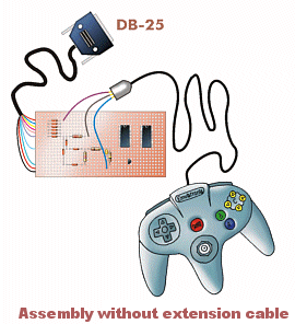
Less clean (more dirty ;-) it is to connect three cables to the points
![]() ,
, ![]() &
& ![]() and to strip enough insulation from the wires and push them directly in the holes of
the female connector on the N64 controller.
and to strip enough insulation from the wires and push them directly in the holes of
the female connector on the N64 controller.
 While this may seem cheesy, I can assure to you that it holds well enough. He is known to
do this whenever we move controllers from the console to the PC, but if you don't want
to spend the money for the extension, this is the only option (other than hacking a connector off a controller
and hard-wiring it).
We arrived at the final part of electronic assembly. Before connecting the DB25 connector to the parallel port (printer port), we will verify all the connections, especially the 4006 IC connections and that the transistor is placed in the correct position. It is very important since if they are wired wrong, the components are liable to 'let their smoke out'. Warned you are;-D
The next step is to install the driver software for the controller.