|
These are a few of the simple things that I found when investigating why some were having troubles using the 2716 eproms in place of the Williams decoder proms. Most of them are just general things that apply to other games, as well, so this is long overdue.
A few feedbacks that I got were that one of the two 2716 eproms loaded with the decoder program would not work, but putting the prom back in place of the non-working 2716... 1 2716 & 1 OEM prom... would result in the board working. No pattern... might be rom 4 position on one bd, while rom 6 position on another. I didn't run into this problem in going through a stack of my own bds, but in checking the bds that people had given up on, I found that they did not work on my jig, either. The problem was a common one found wherever sockets have been in use for years. First off, the sockets that were used most often in the early games were single wipe sockets, meaning that the wipe surface inside the socket only made contact with the inside of the IC's pins. Now given the age of the sockets & the attempts over the years to put ICs in with bent legs, forcing the wipes closer to the outside of the socket housing, and you see that the replacement has the odds against it at the get go.
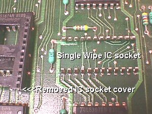 Sometimes the wipes are bent so far in that you can see it without removing the cover. One of the notorious places for this phenomenon can be found on the Pac bds where the sat bds have been inserted into the sockets without the benefit of the intermediate adaptor socket. Another factor is that the proms that have been residing in these sockets for all these years have corroded, welding together a pin or two to the wipe/s. When you remove the prom & break it free from the wipes, they will sometimes not make contact to a new eprom, but mate up to the OEM prom when reinstalled. Now, as if this is not a strong enough current to swim against, then the new eproms are shipped with the pins flaring outward... away from single wipe sockets :-(
 K.... this one I solved right away by making sure that I straightened the pins with my IC Pin Straightener before shipping, since most do not have one of these at their disposal. I do this for almost all ICs shipped to prevent a possible headache. There is a smaller hand held version on the Parts Page Tools. 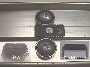 As for the sockets themselves, that's something that has to be taken care of by you....replacing the old single wipe sockets with the dual wipe sockets that make contact on both sides of the IC pins. 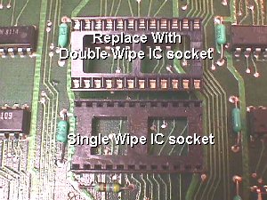 You can readily see the difference in the 2 type sockets & how the dual wipe will ensure that contact to the pins of any IC will be steadfast. 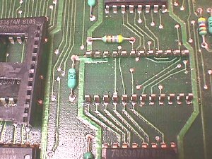 The Williams board has thin traces & small through holes, so normal precautions must be taken when replacing these sockets. I'll go over the basics here again just to be sure. Don't stay heating a difficult solder joint to clean too long... revisit any stubborn ones. The best way I've found to ensure that you do not damage the bd is to incorporate a little help from the boss. Get her standing by with a pair of needlenose pliers. Remove the IC socket cover... gently prying up on it while making sure that you don't damage something else on the PCB. Then reheat the solder joints (solder side of the board) by adding new solder to each socket pin.  Now show the boss which pin you are going to start with & tell her to hold on to it with the pliers while you heat up the solder joint. It'll pop right out for her & she can deposit it into an ashtray or other receptacle & then move to the next pin in line.... and so on until all pins are gone. Next... start at the first pin hole & reheat, use a solder sucker to clean the hole & continue until all holes are clean. 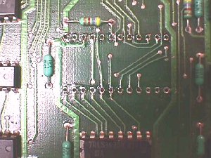 You can hold the PCB up to a light to be sure that you can see through each hole before attempting to place the new dual wipes in them. Also, be sure there are no solder splashes or any excess solder on either side of the board. 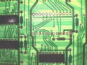 After setting the new sockets, paying attention to placing the notched end correctly, just tack 2 opposite corners so that you can look it over before soldering it in completely. Make sure all pins are coming through & none are bent or missing. 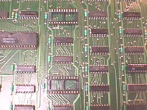 You should end up with sockets sporting their metal teeth proudly like the ones above :-) Take one last look-see around the sockets to make sure everything is good to go. Moving on to the next issue. It seems that the eproms are less voltage forgiving than the OEM proms. This is not a problem with games with switchers already installed as all that needs to be done to correct the problem is adjust the 5 volts up a little higher while monitoring the voltage at the main bd or rom bd. In tests that I performed on my jig I found that the proms would keep on ticking even when the 5 volts was lowered to 4.35 volts & they would even enable when reset at this low voltage. The eproms, however, would not operate below 4.7 volts & at 4.7/8 volts would not enable upon resetting. They need a good 4.85 volts in order to keep on ticking like the older proms. The reason that I did these tests was because a local tech had put a board in a customer's game & it did not power up. He brought the board to me & we put it on the jig & found it worked great. My jig has the option of using the original WMs power supply, so I swapped from switcher to the OEM PS. It still worked fine, so I told him to put it back in the game & check the voltage on the rom bd. As it turns out, he measured only 4.5 volts in his customer's game that had the OEM PS, but it was not one that had been through my shop, so it didn't have the 5 volt adjust added to it, leaving him with no way to correct it. I had him yank the PS & I modified it for him... problem solved. This is one of the few board hacks that I would do, but it is not needed when used with all original equipment. It's only needed when the PS is used to power JAMMA game bds, or just later pre-JAMMA bds, and, of course, if you've modified the OEM WMs bd in a manner such as using the 2716 decoders... if they will not operate without the mod. I don't have any Defender power supplies left to illustrate the mod, but it is a simple one only requiring that R2 be replaced with a 5K pot. Just set the pot to midrange & adjust with a meter after powering up. My linear supply is mounted under the monitor on my jig, but I will try to get a pic of it to place here. 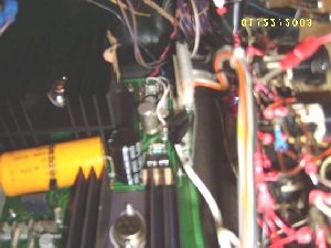 Well.... as it turns out, my Sony didn't want any part of capturing a pic up in this dark hole under my jig monitor, so I used Alice's camera with flash... upside down & without being able to see what I was shooting. It didn't make for the best pics, but hopefully you get the drift of things. 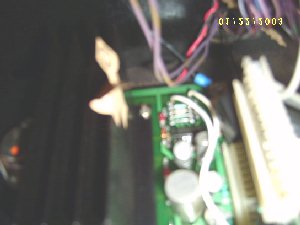 This particular one on my stationary bench jig is wired into a 5K pot mounted on the control panel along with a 12 volt analog meter for monitoring the output at a glance. The white married pair of wires simply take up residence in the thru holes where the R2 resistor was removed and then the other ends tie to one side & the center tap of the mounted 5K pot. 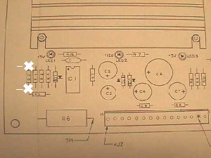 Maybe this layout pic from a manual will point out R2 a little better than the fuzzy pics :-( As the WMs power supplies came thru the shop... back in the day... I made the mod on board by using a 5K thumbwheel in R2 spot leaning to the left, braced & stabilized with a gob of hot glue. Well... it's taken me somewhere between 5 to 10 years to get this finished & posted, so I sure hope some of these general solutions & tips will be of use to hobbyist.... at least a couple :-() The next article I plan on finishing is on the cheap audio amplifier that I have explained in email at least a hundred times over the past 10 years with mixed results, some get it, some give up, so it's time to put some pics to the project enabling more people to get it. Hmmmmmm.... I kept a daily journal during Katrina down time devoting a minimum of one hour a day... some days 3 or 4 hours... and at the rate I'm going I probably won't live long enough to transcribe it :-( Maybe I should learn to type faster :-) Happy Gaming... |